|
||||||||||||
|
Home | ||||||||||||
|
||||||||||||||
|
|
||||||||||||||
|
Cab Controls |
||||||||||||||
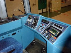
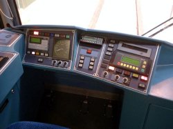
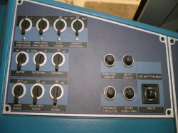
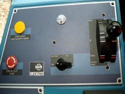
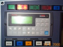
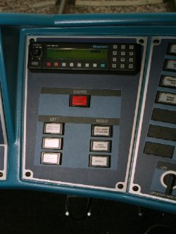
Contrary to many peoples beliefs, the trams are not driven automatically, nor does the tram have a steering wheel. The cab layout is centred to give the best visibility with the main Traction/Brake controller on the drivers left. The whole of the Cab layout has been moved to the right by around 80mm, including the seat compared to the K-4000 tram in Cologne, to give the drivers better all round visibility. On the drivers far left are a series of switches for things such as heating and lighting as well as fault override switches, pantograph up/down, wash mode and others. Also on this panel are cab heating controls and electric control of the outside mirrors. Ahead of this to the left of the driver is the main Traction/Brake Controller. Forwards for power, backwards for break with a hazard brake position, marked in Red beyond the braking region. The Emergency Stop (Red) and Emergency Pantograph Down (Yellow) are to the left of this. Also in this position, a key switch. Nothing works without a key inserted. Below this is a mode switch with Off, Auxiliary which powers up heating and lighting but not traction power, and Normal. A reverse, shunting option was disabled before opening. Ahead of the driver is a microphone for both the PA and radio communications. The trams main VECOM (or Vehicle Computer) is next. This allows the driver to enter Route, Driver and Running number information as well as controlling data downloads of the timetable and Route in normal operation. The small screen usually displays the drivers punctuality at each stop in 15 second increments. A speedometer in km/h is provided to the right of the Vecom. Trams are limited by speed limiters to just over 80kph which is the maximum speed on any part of the system. Below the VECOM are buttons for Internal PA, External PA, Cab-Cab Intercom and Passenger Intercom which are pressed when speaking. Below the speedometer are switches for the headlights. Above the VECOM and speedometer are various indication lights including Indicators, Lights, Door Open/Closed, and Stop Request. In the centre section at the top there is the tram radio - see the Radio System page for more information. Below the radio are the Door Control buttons. Doors on each side either all or just the front set, can be released or opened and closed. Door control must be a two hand operation requiring the central button and a release button on the far left or far right of the desk to be pressed simultaneously. To the right is the IBIS fault display and associated Fault Acknowledge and Cancel buttons. In normal circumstances, this displays "Tram is Ready for Service". Any fault is displayed with both a number and a description. Common ones are "Passenger Communication Pressed" and "Minor Fault Recorded, Trailing Bogie". Faults are categorised into A, B, and C faults. A faults are serious and require immediate attention. B faults are usually dealt with quickly and controllers will decide with Bombardier Engineers on what needs to be done. C faults are generally trivial and are logged for attention overnight. One amusing fault is "Error, Too Many Faults!!" Below this display is the IBIS or BISS unit which controls the on board information. This includes the Next Stop displays and announcements as well as the destination blinds all round the tram. Below the IBIS are illuminated buttons for manual sanding, full beam headlights, hazard lights, fog lights and on the far right magnetic track brake. Below these are the controls for the left and right indicators, the windscreen wipers and screen wash. In addition, the driver has three foot pedals available for Radio Call, Horn and Bell. Should the driver have problems with his normal controls, then the emergency red button can be pressed to bring on the track and disc brakes along with the dispensing of sand and should the driver see a problem with the overhead lines then the yellow button can be pressed to lower the pantograph so it is not damaged by the obstruction or fault, whilst also going into hazard braking. If drivers take their hand off the Traction/Brake controller an alarm would immediately sound and should the driver not respond within 3 seconds, then the hazard brakes are applied automatically. In the event of any emergency situation such as a Road Traffic Accident occurring, then a removable disc within the 'Black Box' in cab 'A' can be decoded as this holds the control data from the last hour of operation. This is usually recovered by British Transport Police and it can be connected up back at the depot showing exactly what speed the tram was doing and what actions the driver was taking. |
||||||||||||||
|
|
||||||||||||||
| Designed by Trapdoor Internet Services |